Underground sport center
In the fall of 2018, A2M offices received the mission to build an underground sport resort. During the really early stages of design, the architects came up with the idea of a tensile alike roof that would cover the whole complex. This is where Grasshopper came to a use.
As the early phases of conception began on this project, I was integrated in the team to handle some Grasshopper3d work.
My work for this project consists in creating a tensile-like roof that covers the entire sport resort, and since the project is at its beginning, I had to develop a workflow that would allow the architects and myself to update the model quickly each time something changes.
So here we start with the basic geometry that is extracted from a CAD software. Four plans (one for each level) are being updated at the same times architects modify the program. They represent all the rooms of the program, and appear on the level from where we can access them.
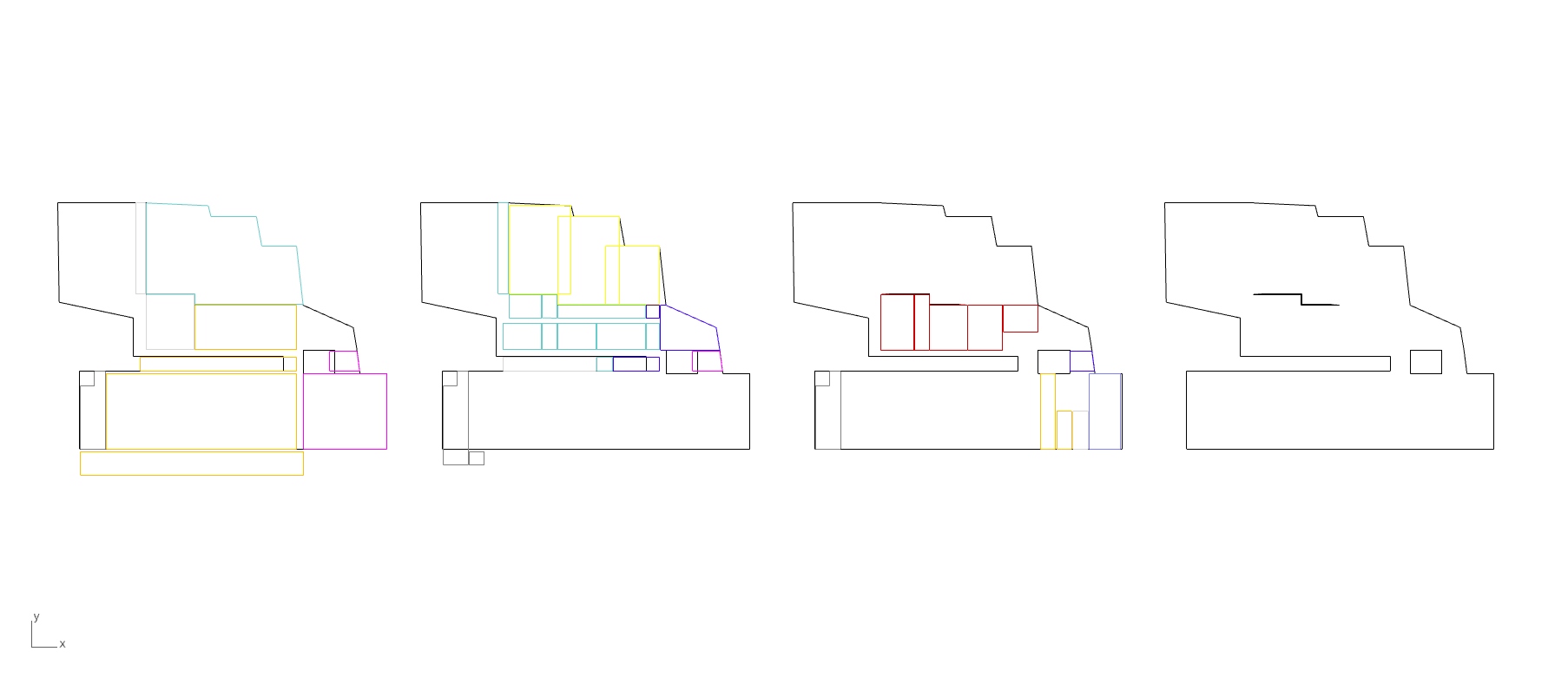
The four plans of the projet (one for each level).
Since the CAD software used for the plan vues is Microstation (and that we are in the early stages), the plan views do not have any 3D information. So we came up with an Excel file that would be updated, this time manually, by the architects and/or myself. The workflow developed with the Excel file has been made so that any one could update the sheet and therefore the 3D model.
When the new plan vues are reloaded in Rhino, they automatically are identified as different level, based on their position. Lowest to highest, left to right respectively. The (simples) geometries inside are classified upon their named layers. As all of this happens in the background, numbers then appear on each room in order show the person behind the screen what is the order of the rooms for each level.
This very person also happens to have a specific Excel file opened at the same time, the one showed below. In this files we gather some basic information about levels, height of the rooms, additional structures space and other margins. As you can see, there are two Excel tables : a small one that contains default values, and a bigger one containing some override values for the specific rooms, ordered by level. If a “0” is found in the override table, the value corresponding in the default table will be used for Grasshopper3d. The numbers that appeared in the rhino environment, explained previously, correspond to the row numbers in the Excel document. (Soon online)

When all the required data is filled in the excel tables, we return back to Rhino and Grasshopper3d. There, at a click of one and only one button, we get a simple geometry like the one below. Please notice that the colors correspond to the level of each rooms. Moreover, the blue edges show us the space needed for some structural element, while the red ones represent some additional margins. All these 3D geometries come from the combination of the CAD plans and the values in the Excel file.

From there, we are ready to click on another button. This time, its function is to build a simple mesh that covers all the geometries while staying as close as possible to them. This way the simulation will run in a more predictable manner.
The outer limit of the mesh correspond to a poly-line that came with the CAD import. When pushing the button of the previous step, Grasshopper tries to give a Z value to each corner of this poly-line so they match the height of their surrounding geometries. Some corner can also be selected and modified if this will ever be needed.
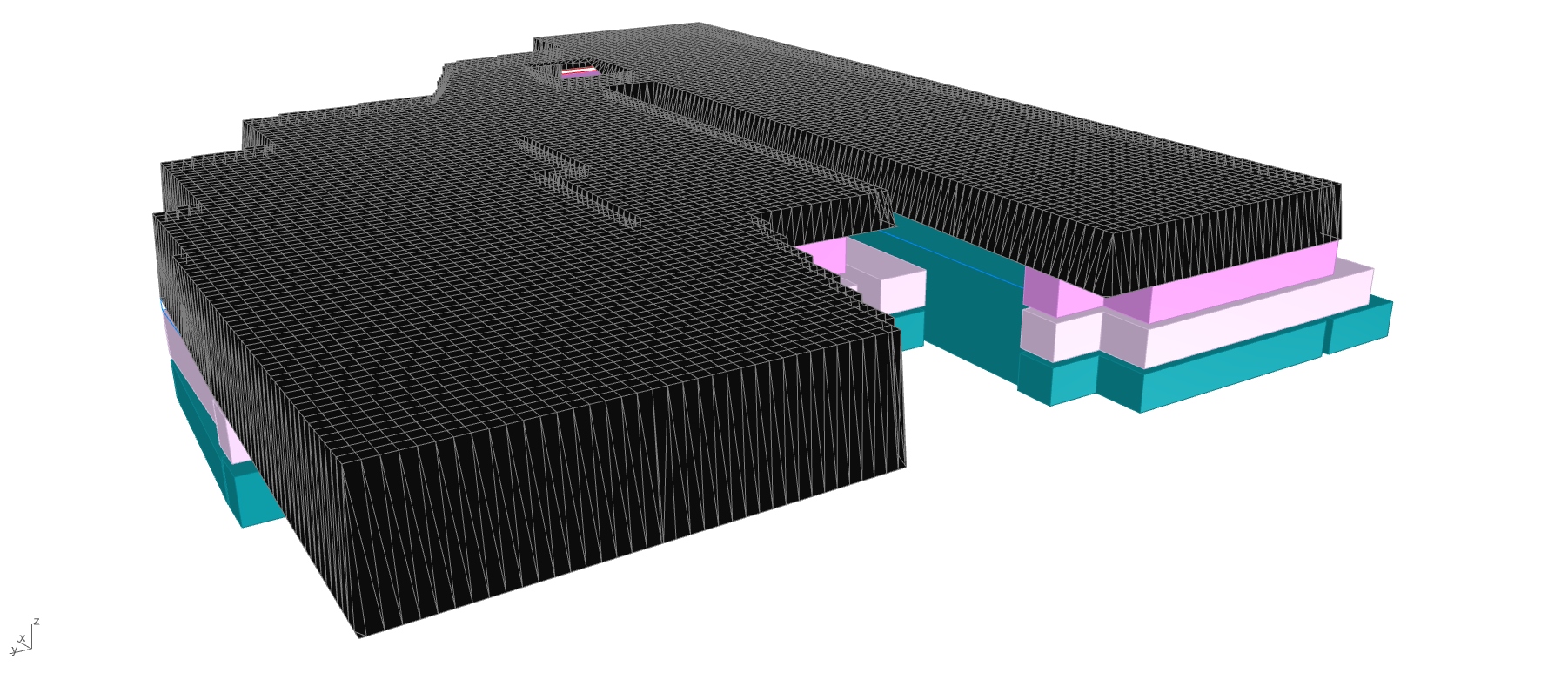
Mesh ready to be relaxed
Another button is now waiting for us ! This one triggers the relaxation of the mesh while making a collision simulation to all the geometries.
For this, I decided to use FlexHopper. This Grasshopper3d plugin allows these kind of simulations while relying on GPU calculations, which is a lot faster than through CPU. The relaxation here under always took less than 10 seconds on a rather slow portable computer, which is quite mind-blowing considering the thousands of points and springs of this mesh.
Huge thanks to Benjamin Felbrich for this amazing (FREE) plugin !
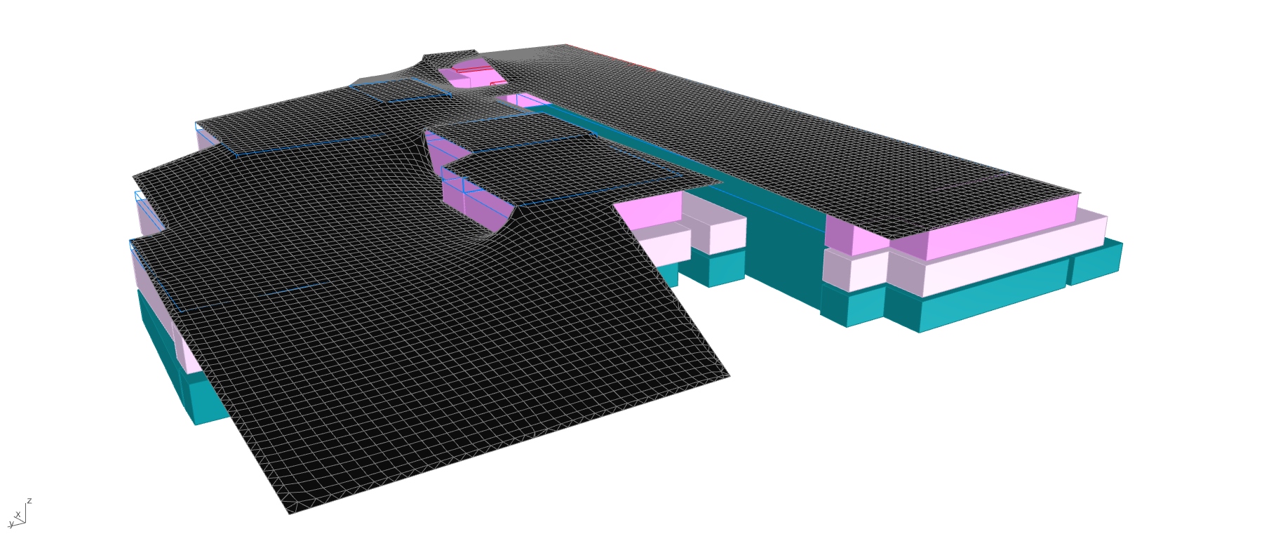
Relaxed mesh
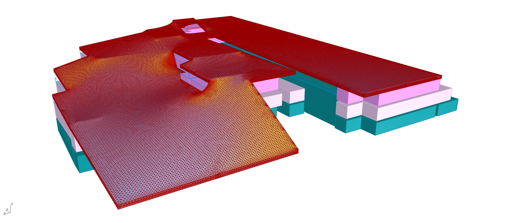
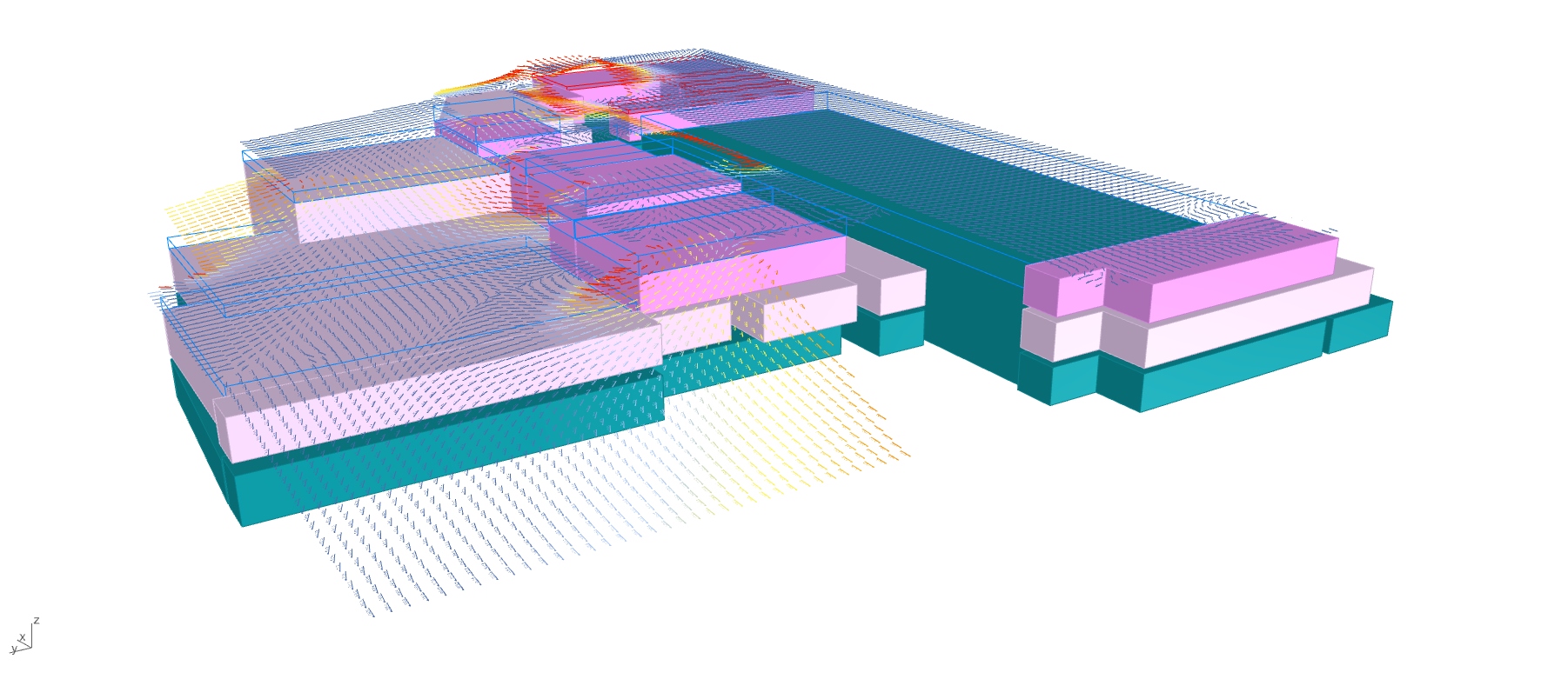
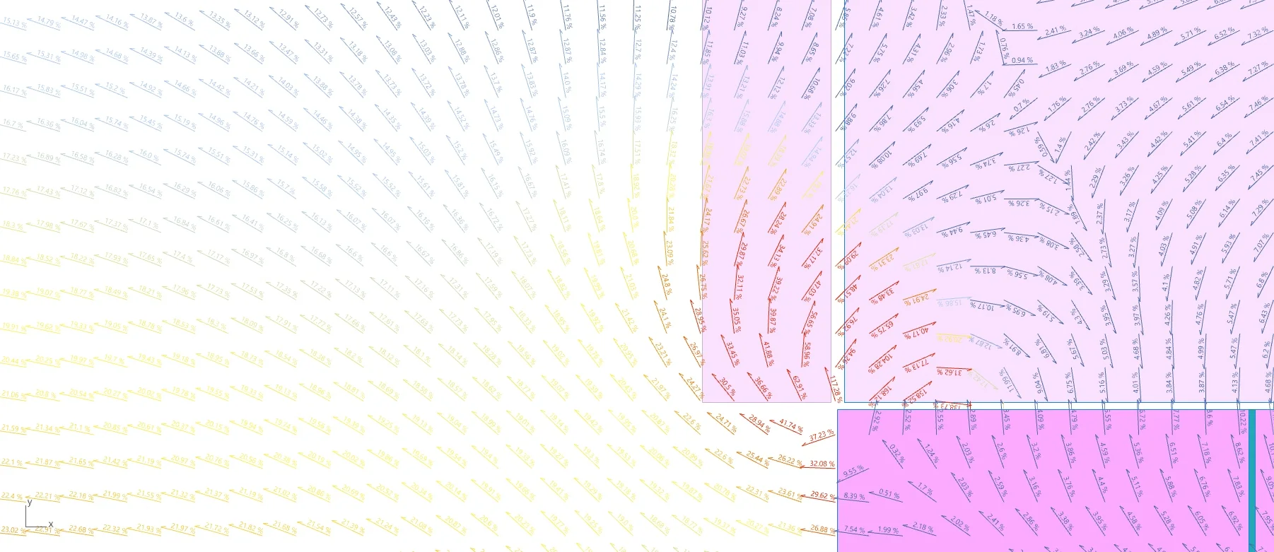
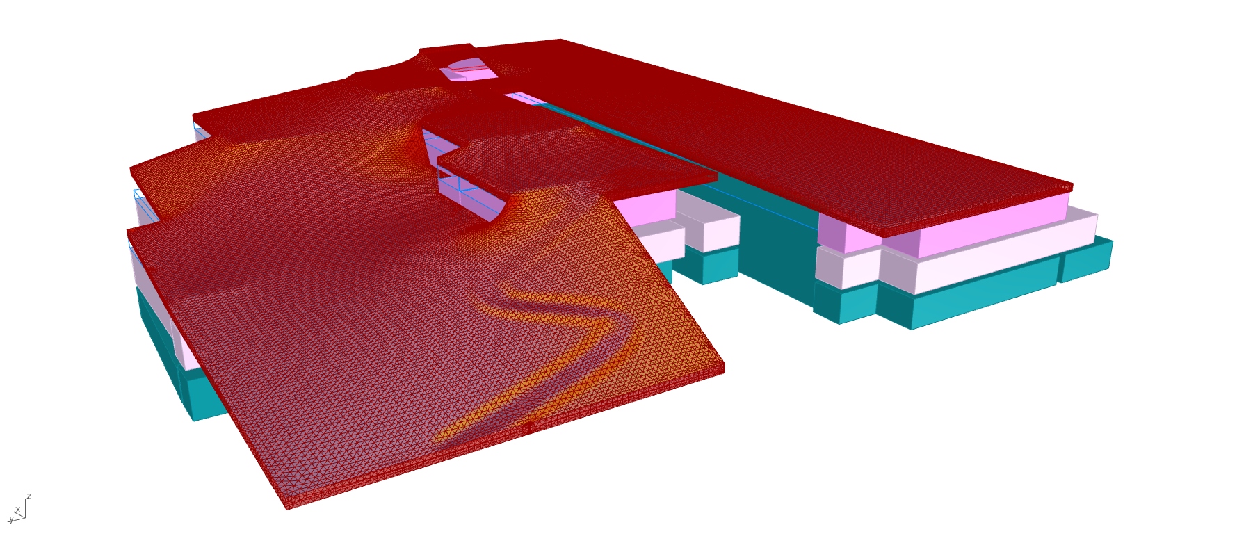
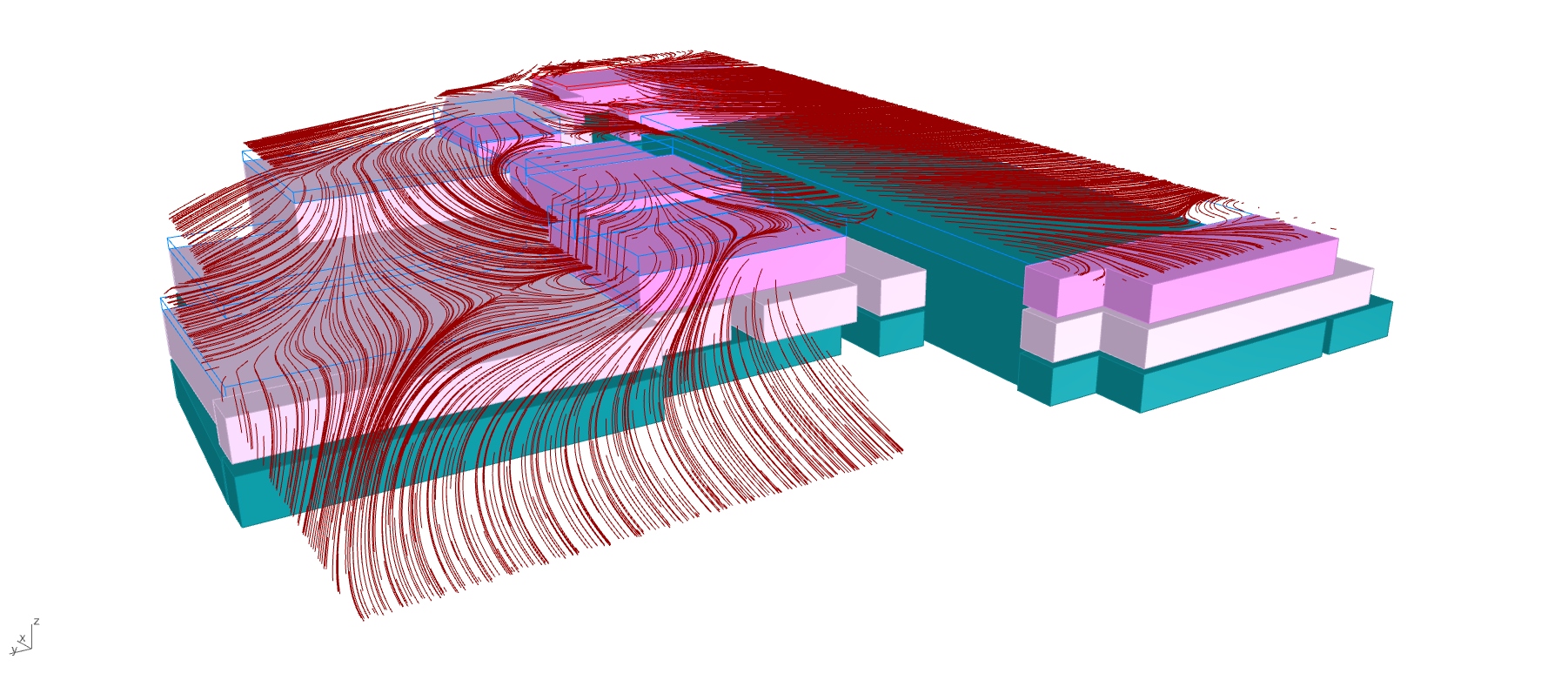
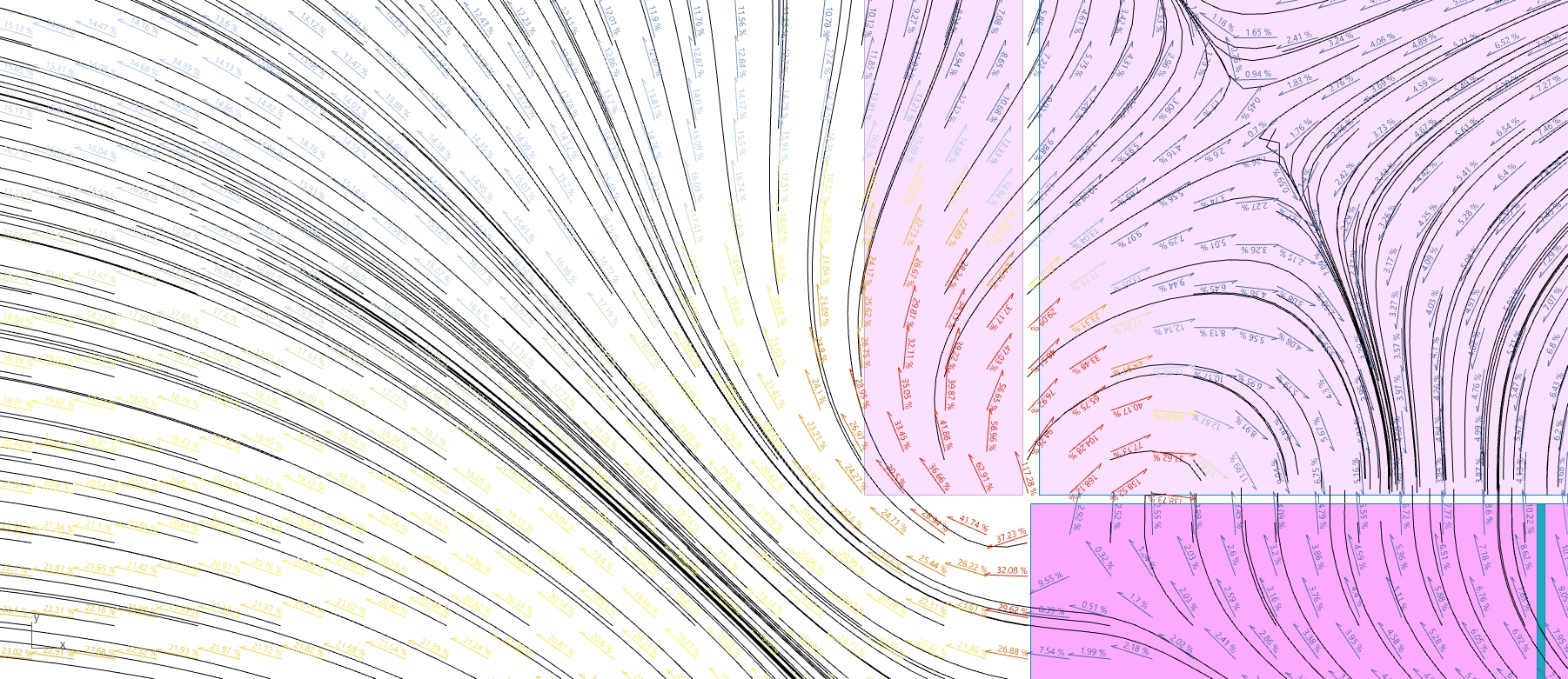
We have now finally arrived to the very last button ! This one creates a 3D closed mesh based on the last simulated one, and applies a few analysis/modifications like : slope angle and its direction, water flow lines, 2D contour lines, path modeling, 2D sections for further CAD drawings, and more.
Here under some of them.
As said at the beginning, the project is still in its early development. It has changed a countless amount of times because of program mutations, plan optimization, new site connexions and costs reductions. Yet, most of the time, the definition could take the changes without dying. The model has been at the end completely recoded as a lot of settings were not needed anymore and as we started to go for more precision.
ehm… I lied to you, there is an ultimate last button… The cooking master button, which bakes all the geometry to a dated layer with sublayers named after the ones that will use this geometry after me and out of Rhino. Those sublayers also got sublayers named after what the geometry inside actually is. I believe this is way more convenient for the architects or draftmen who will use the produced geometries and because it only takes me the time to set the Grasshopper logic once, compared to them who would have to sort everything every time !
That is it for now on this secret project… As I’m trying to keep this website updated as much as possible, the next steps of this project should be added as it grows up.

Antoine -

