Pont de Bondy
The Pont de Bondy team summoned our Compute department, and I was tasked on helping them resolve the roof geometry, the facade and a schematic 3d geometry of the ETFE roof in the middle.
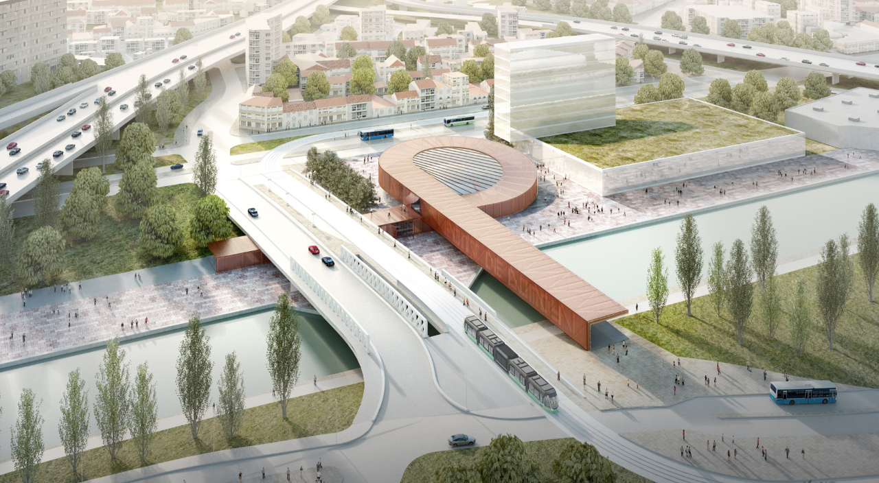
© BIG
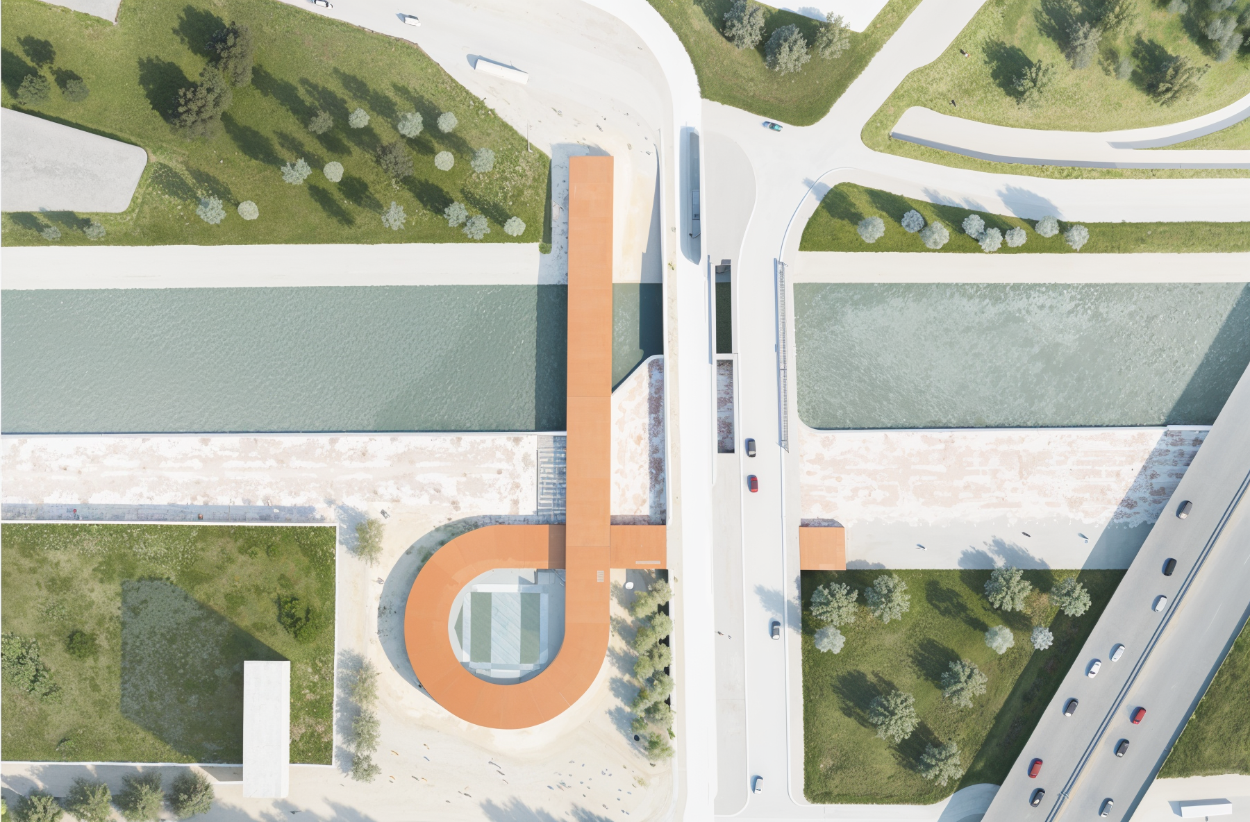
© BIG
Pont de Bondy is a somewhat “older” project from BIG that has been sleeping for a few years. The model I received had been made during the competition phase, coming with all the unsolved geometry problems that you’d expect; It was not following the concept drawings, wasn’t taking accounting for construction and wasn’t even following the structure. Just the regular good stuff.
THE ROOF
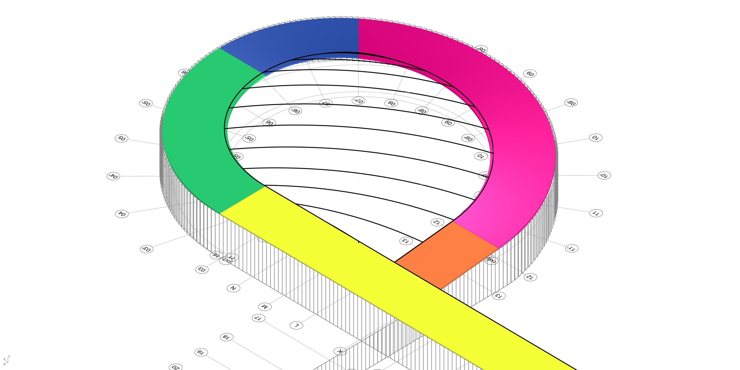
The first step was to get to know the project, get the actual structure planned for the ramp (mostly just axis) and the general intent of the design. The designers described the ramp to have 5 different steps:
Constant slope straight (orange)
Constant slope turning (pink)
Varying slope turning (blue)
No slope turning (green)
No slope straight (yellow)
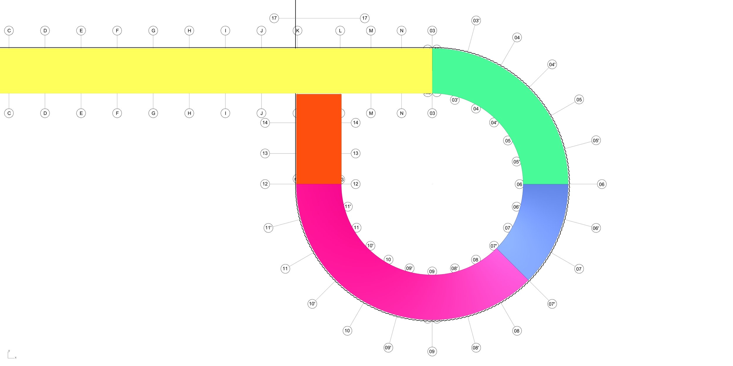
Top view of the solved geometry, with the 5 described steps
The problem might seem trivial, but ended up being slightly more fun to solve than expected. One major detail is that all the transitions would have to happen on radial axis (where columns are) that had been defined by the engineering team, since the transitions of each element meant also different built elements and sometimes different construction methods. Moreover, the solution had to fit under fixed heights and min / max slopes to fix the current design.
Few designs have been explored, here under the two main candidates. Black lines represents contour lines.
Note: on the dropped version, the outside edge goes up at a lower rate since it has a longer distance to achieve. The blue sections are the only place where slopes are changing from sloped to flat.
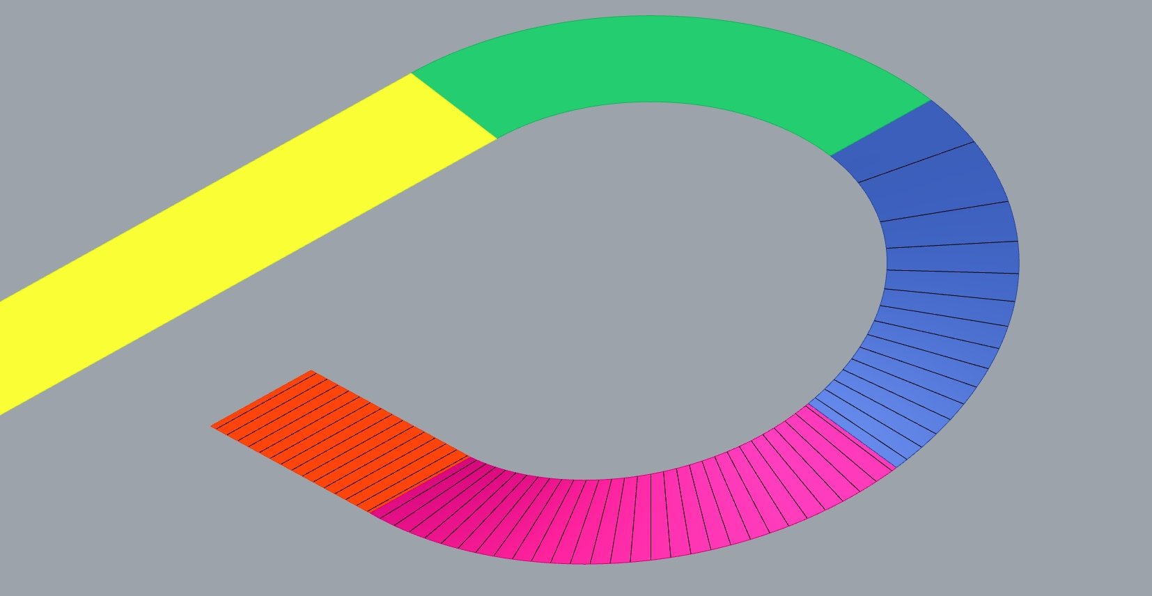
Selected design: center line reference for slope

Selected design: front view
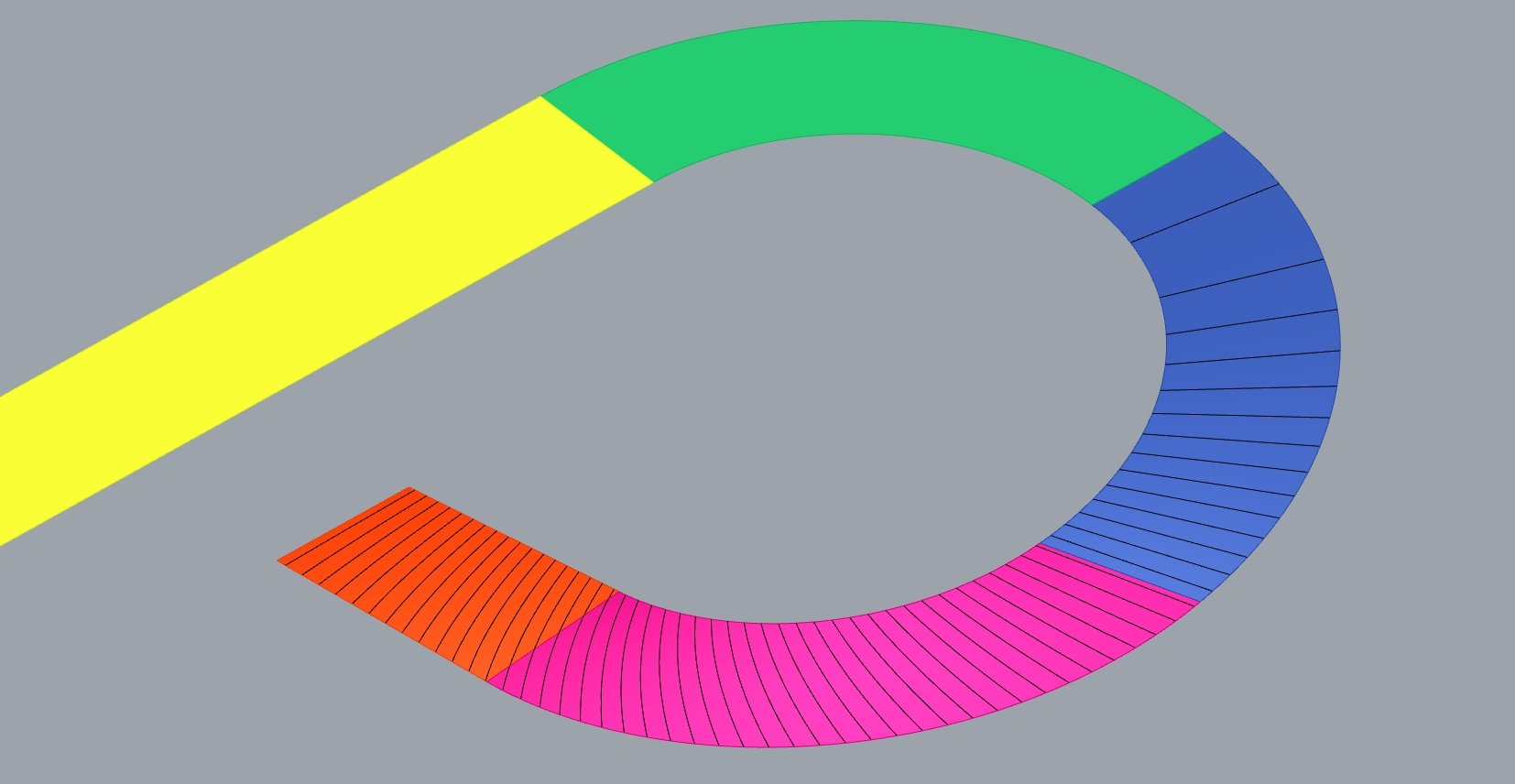
Dropped design: edge lines reference for slope
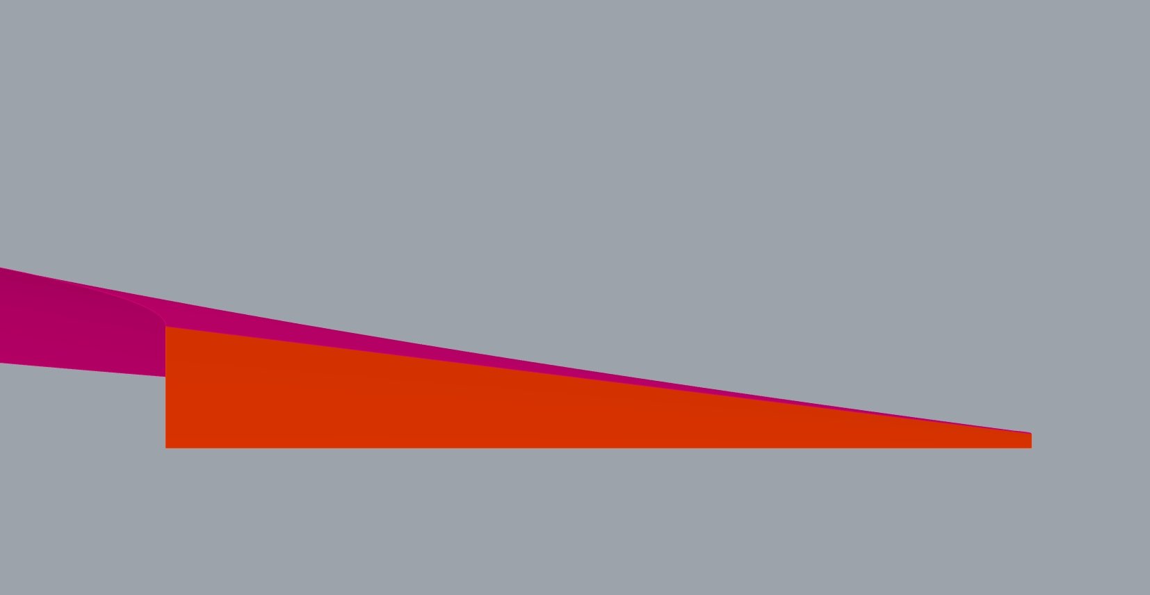
Dropped design: front view
The dropped design (although exaggerated in the previous images) guarantied a better edge continuity between some steps. The selected design is much more in line with constructability, which was the decisional criteria.
For slightly more detail, in order to fit all the constraints, the design has been solved unrolled and involving a small optimization to find the best position for the circle (responsible for the blue part), visible on one of the images hereunder.
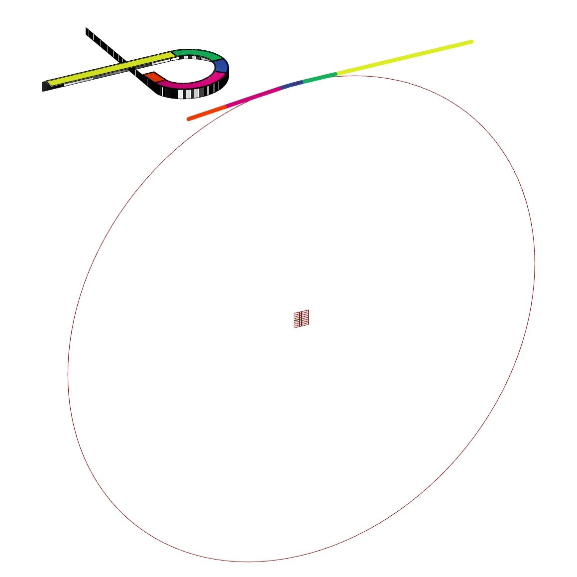
Optimization: abstracted to finding the center (and the circle) on a plane
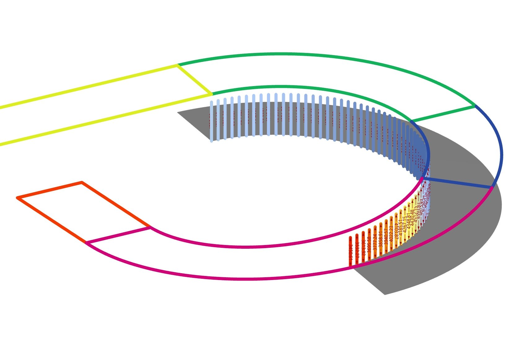
Another constraint was ensuring indoor height limits while finding the solution
THE FACADE
Contrary to the renders above, and as you might have spotted in my images, the outside facade isn’t blind wood panels, but many thin vertical windows. Once again the current plans were not following the structure, and the sizes were all over the place, which is sort of expected in competitions. The design team also needed the window panels to rotate on a vertical axis to be at an angle from the edge of the roof.
The todo list:
Find relevant vertical divisions while following the structures (columns), which means different widths
Use construction details to locate the panels in 3d
Define and model the rotations
Build excel file to track and compare designs
Push to Revit
After finding the mullion divisions so that columns always meet with one mullion and located all the elements, I worked on the tilting of each panels relative to the curved facade.
Many parameters were available, but in the end the panel transition would happen in one columns interval, twisting from 0 to +12 degrees.

blue: perpendicular angles to facade | red: varying angles | green: fixed angles

gradient colors represent the angles of the panels to the facade (yellow and green curve)
Some more images hereunder illustrating some of the differences between the panels.
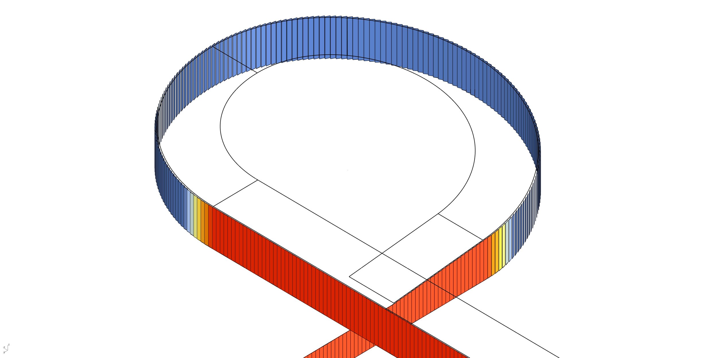
Relative angle difference
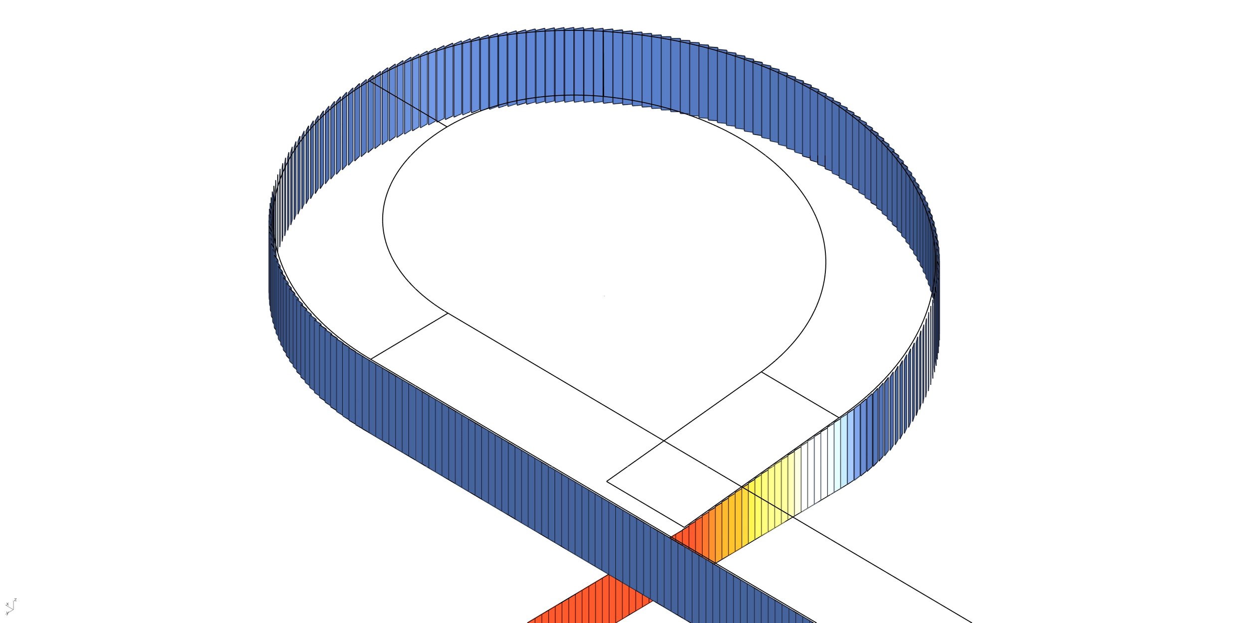
Panel heights
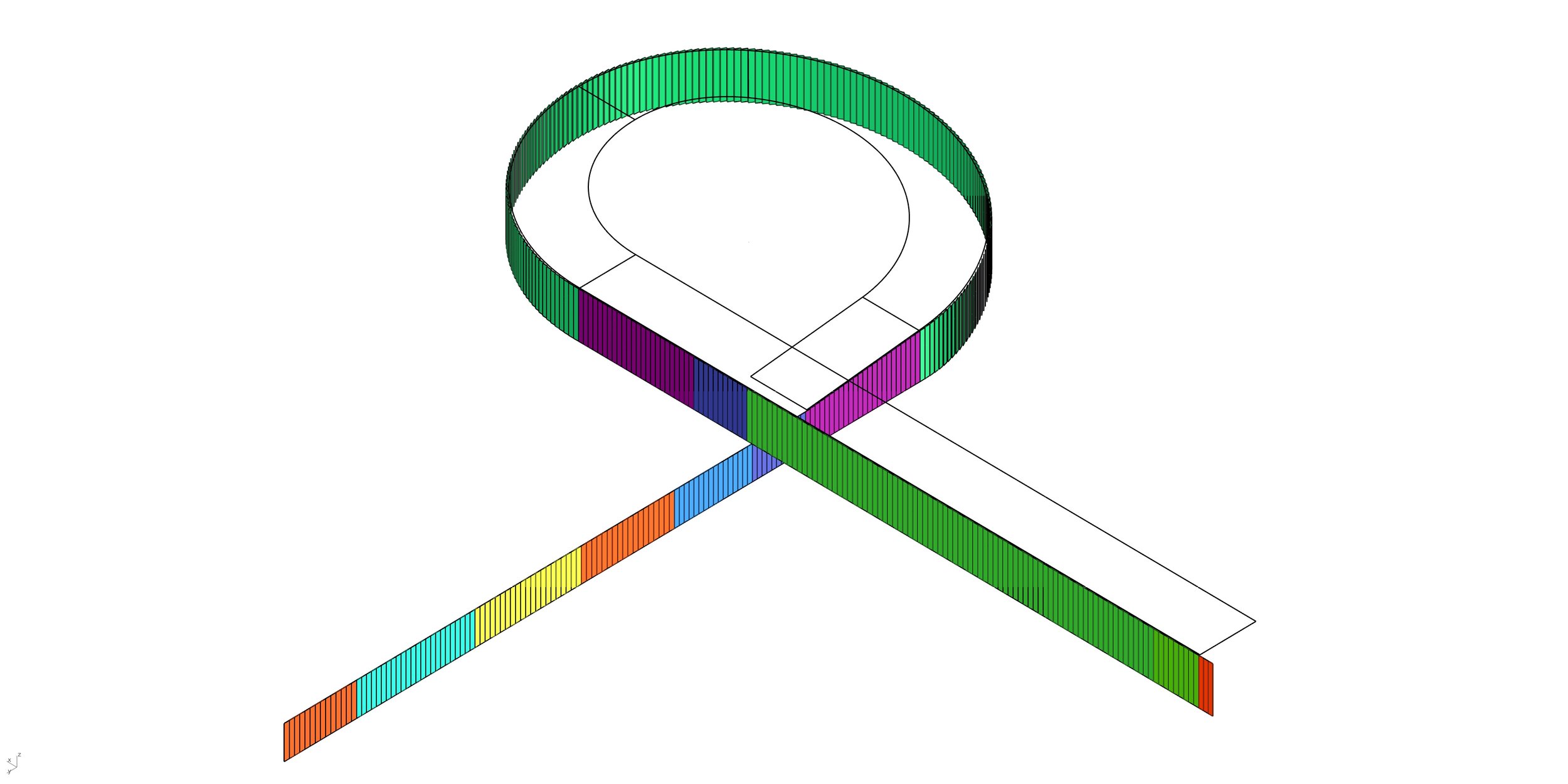
Absolute panel widths (less variants when tolerances are w
Once the design was slowly settling in, BIM discussions started to arise. Soren and I evaluated the possibility to rhino.inside the geometry using a custom family, but in the end opted for a temporary intermediate file that keeps all the data to reconstruct the elements in Revit with a simple Dynamo script.

Revit image
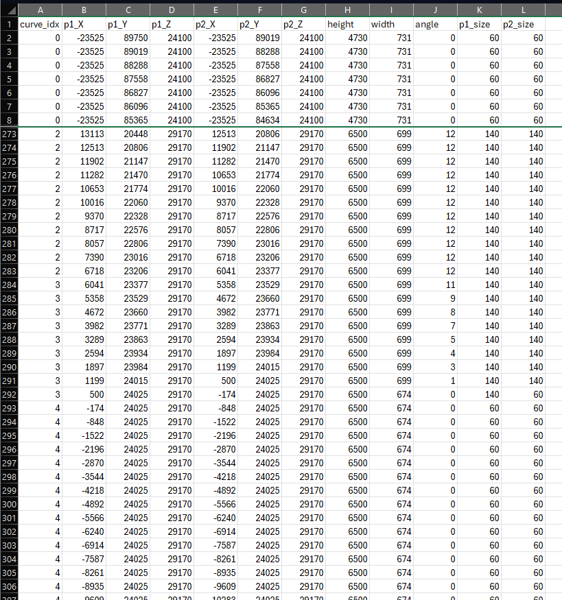
Automatically updated Excel file that lets Rhino and Revit share geometry
ETFE ROOF
The EFTE roof was supposed to be a very quick and dirty yet simple modeling to have some visuals of it in the Revit file for administration documentations. Details were rough, the deadline was short and the main goal was for inaccurate views and sections only. I therefore decided to stay off of kangaroo and and find a geometric approach that would look somewhat like layers of inflated elements.
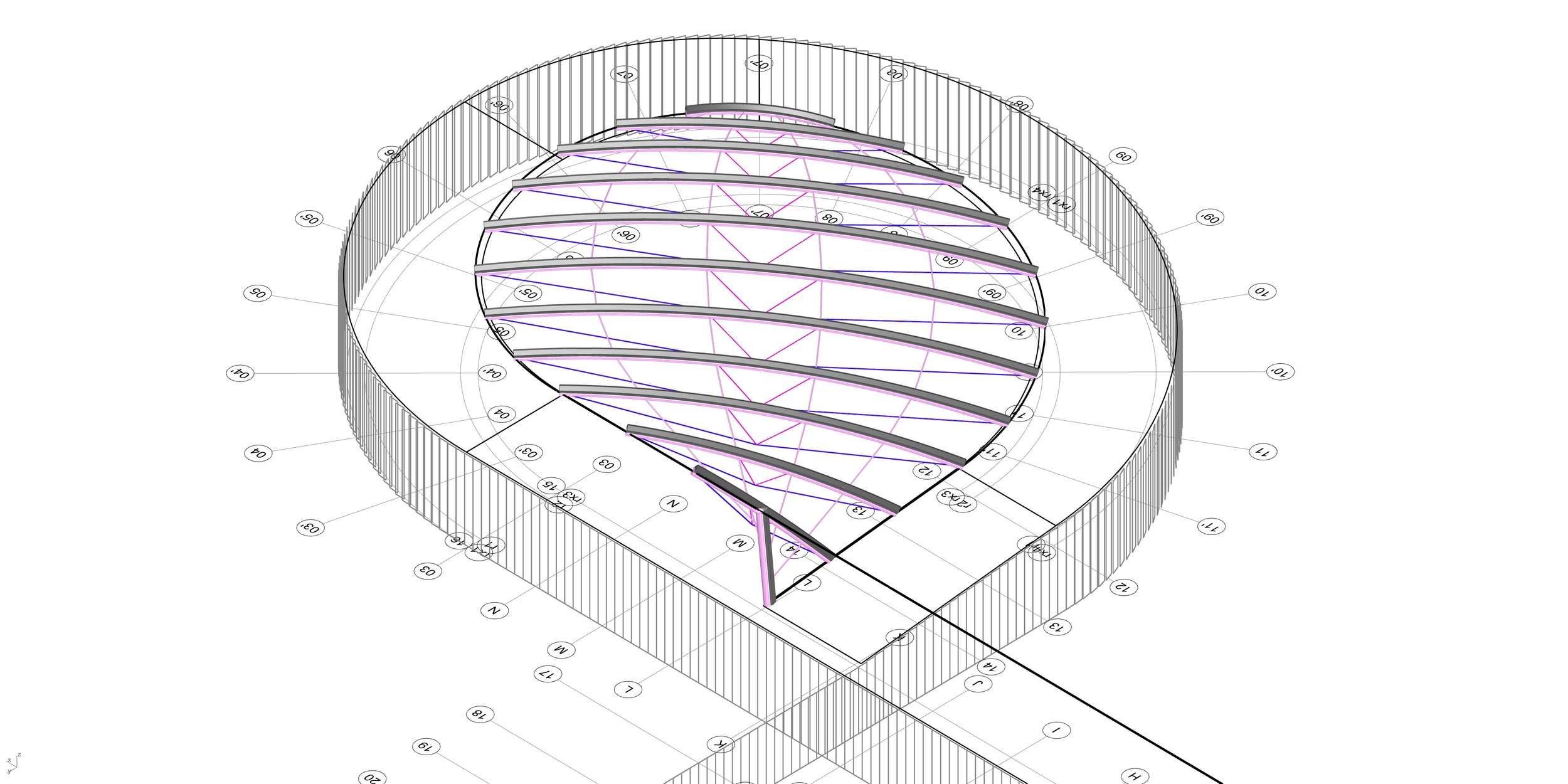
Structure elements, matching the project’s structure (despite not necessary)
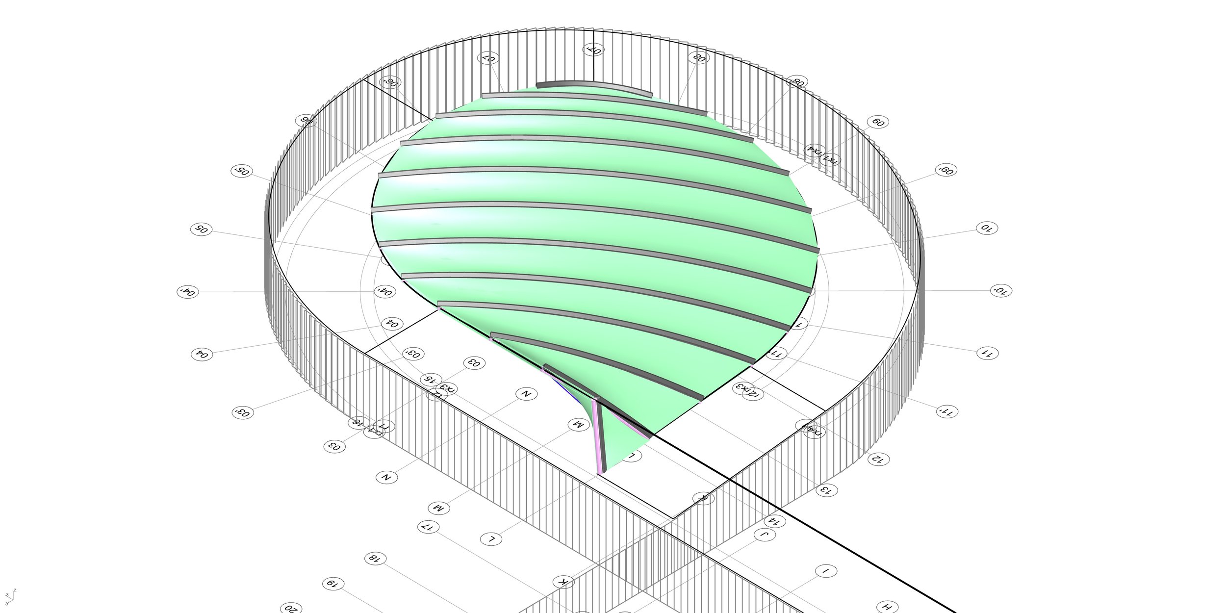
First two bottom layers
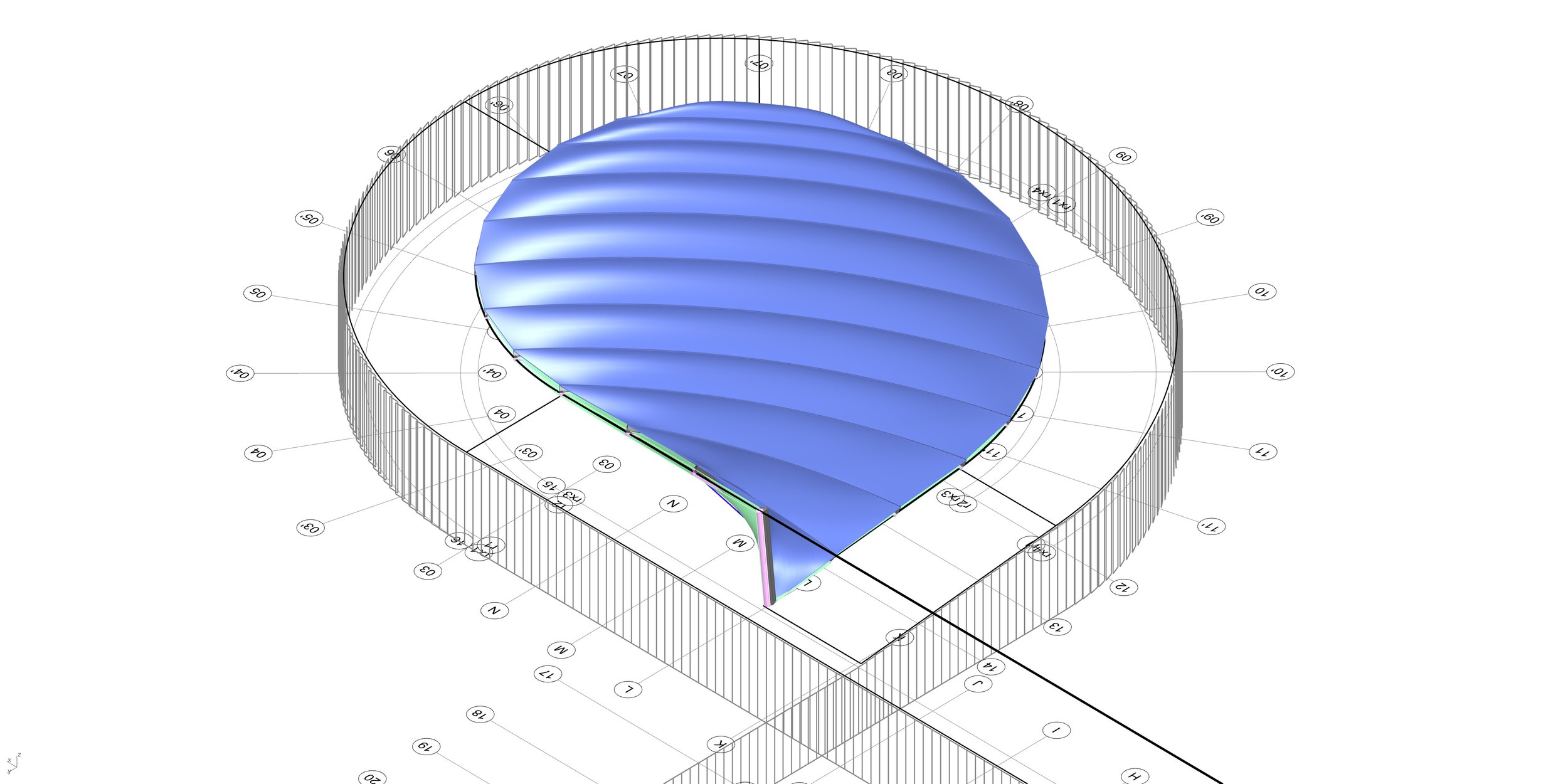
The fake inflated ETFE layers
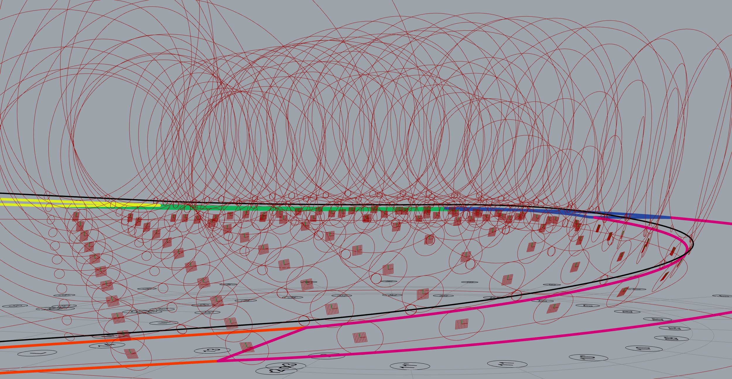
Well, what is this
All the elements were sent to Revit as a generic model. All the geometry (7 different layers in total) were all non intersecting solids. All the pipe geometries required a special attention (and modification) in order to be rendered properly by Revit by default.
Antoine - 2024
